Prototyping & Assembly
Step by step assembly of the finished robot:
2nd Iteration
.JPG)
UC San Diego · ECE 5 · Spring 2026 · Team 5
We built a line-following robot from scratch — soldering, 3D printing, and a PID control loop tuned by hand. Here's what we made:
From Chapter 1–2 submissions: an autonomous line-following car built from scratch — breadboards, solder joints, 3D-printed parts, and a PID controller we tuned by hand. No promises on the first 15 tries.
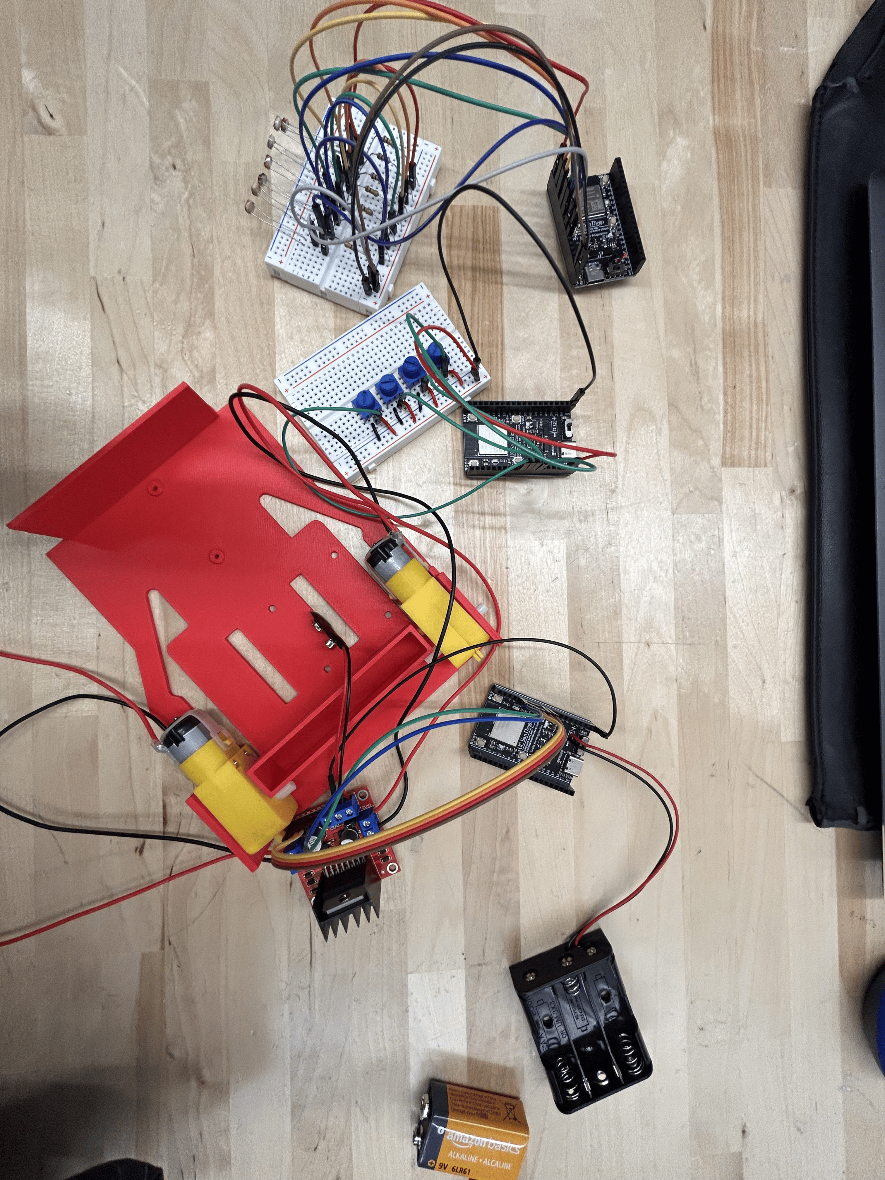
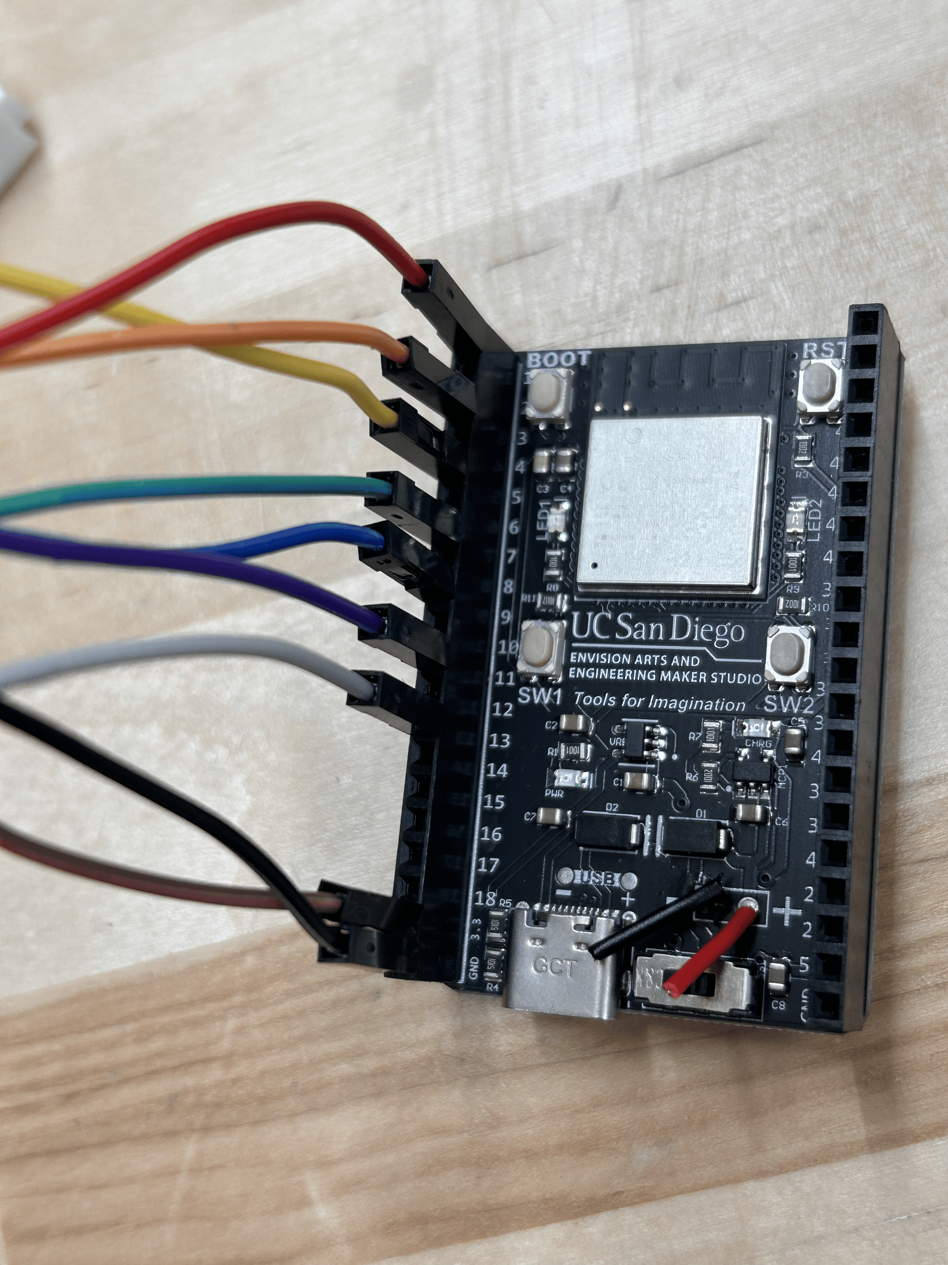
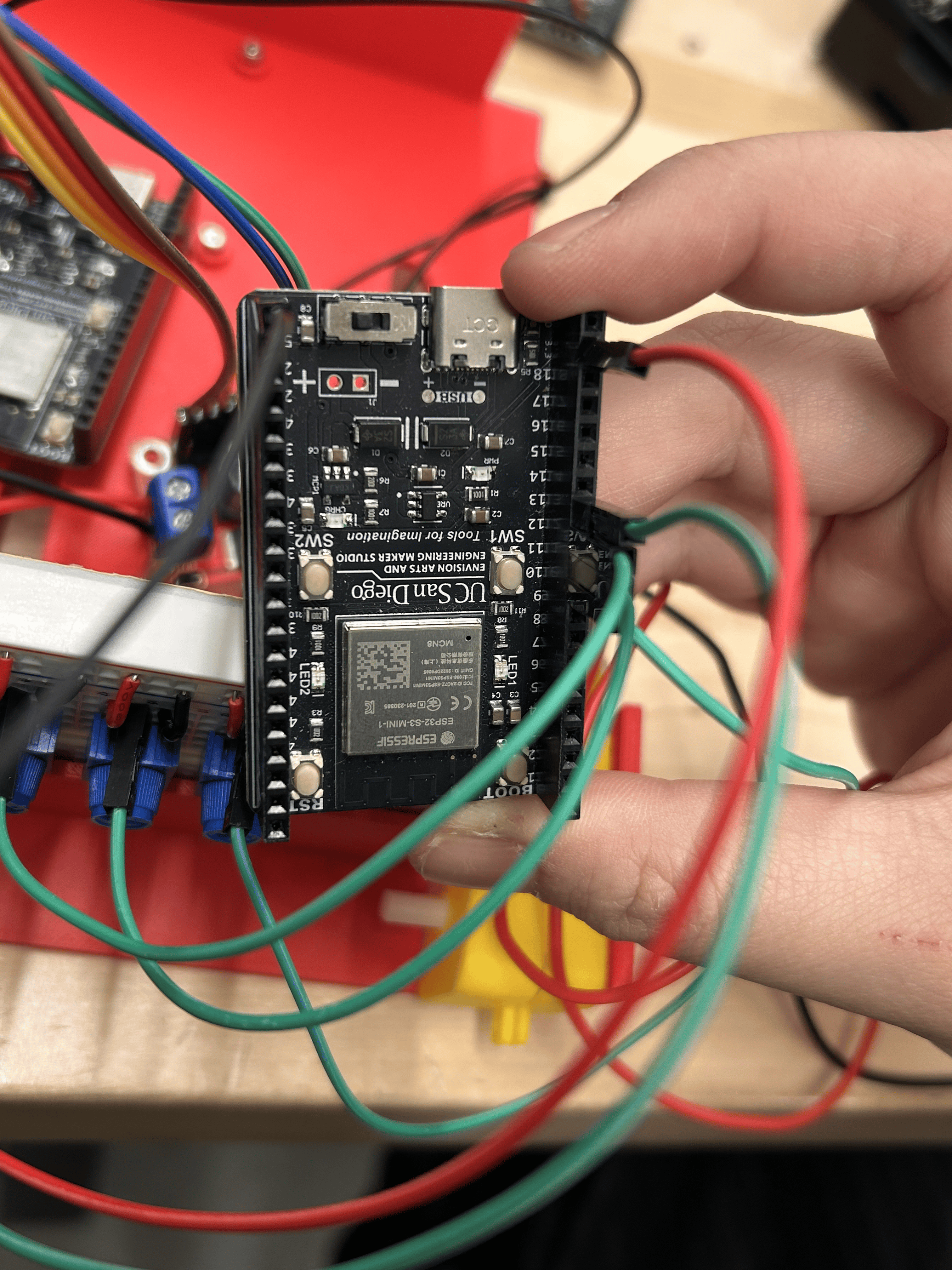
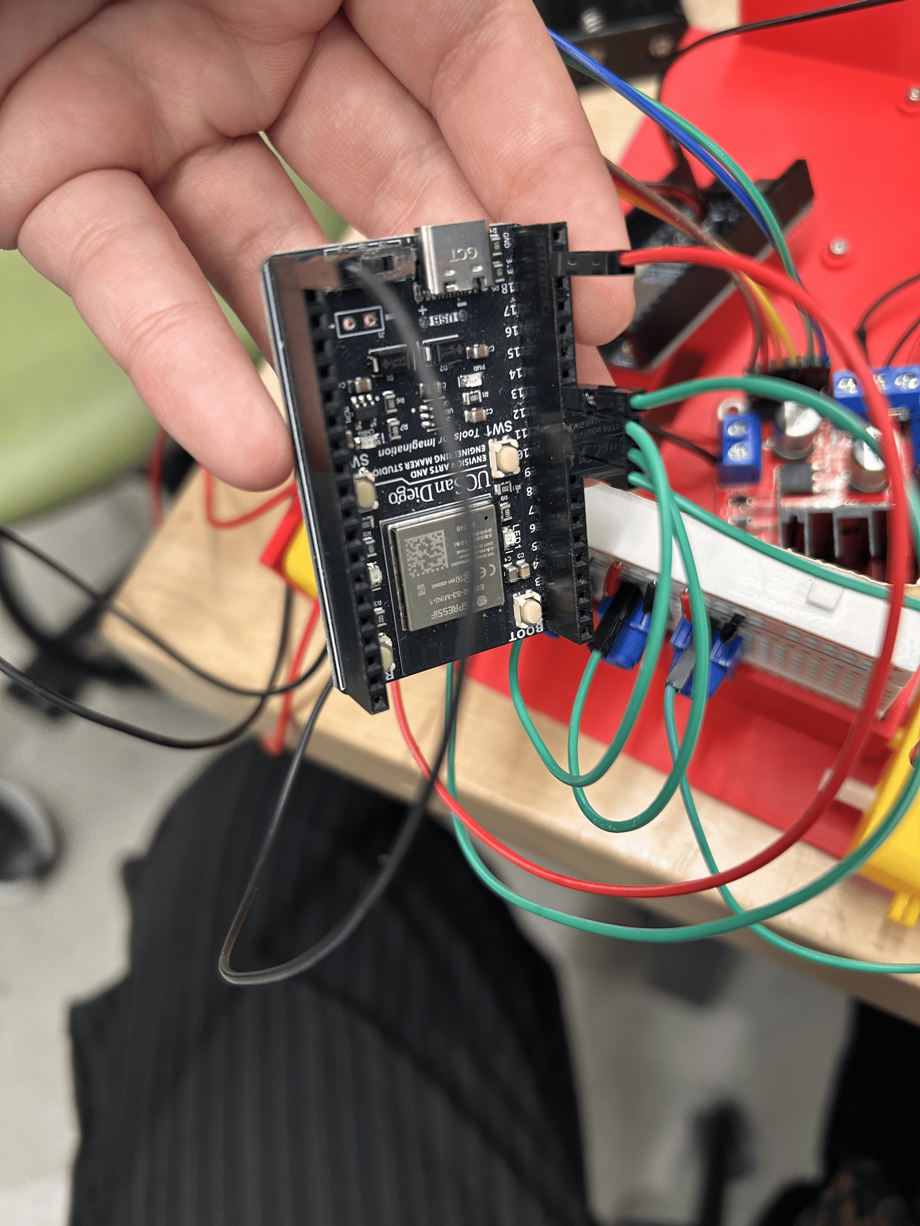
The brain of the robot. Reads all sensor inputs, runs the PID control loop, and sends motor commands — all over Arduino IDE via USB-C.
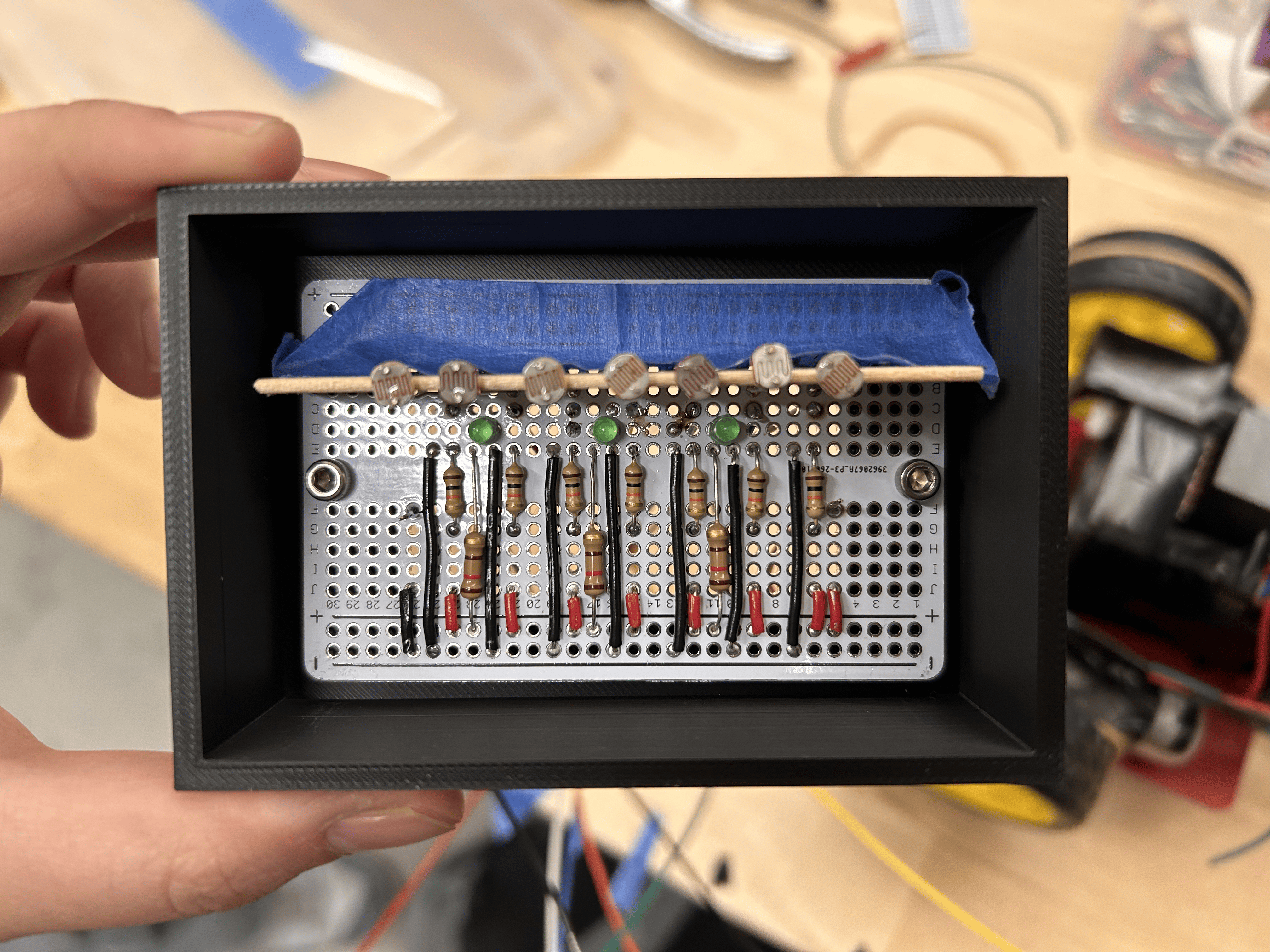
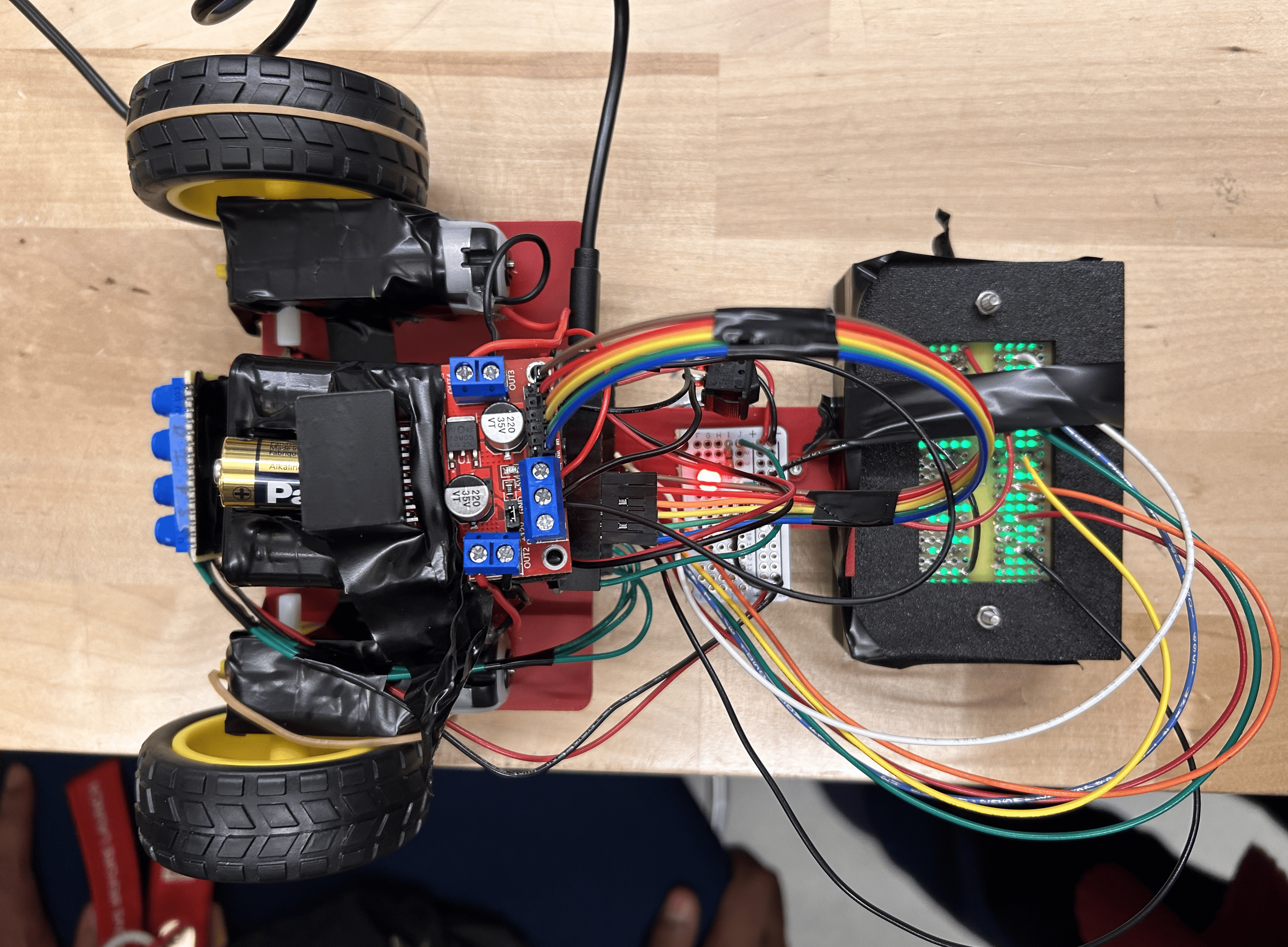
Voltage dividers with 10 kΩ resistors form a sensor array across the front of the robot. They detect the contrast between black tape and white surface to keep the bot on the line.
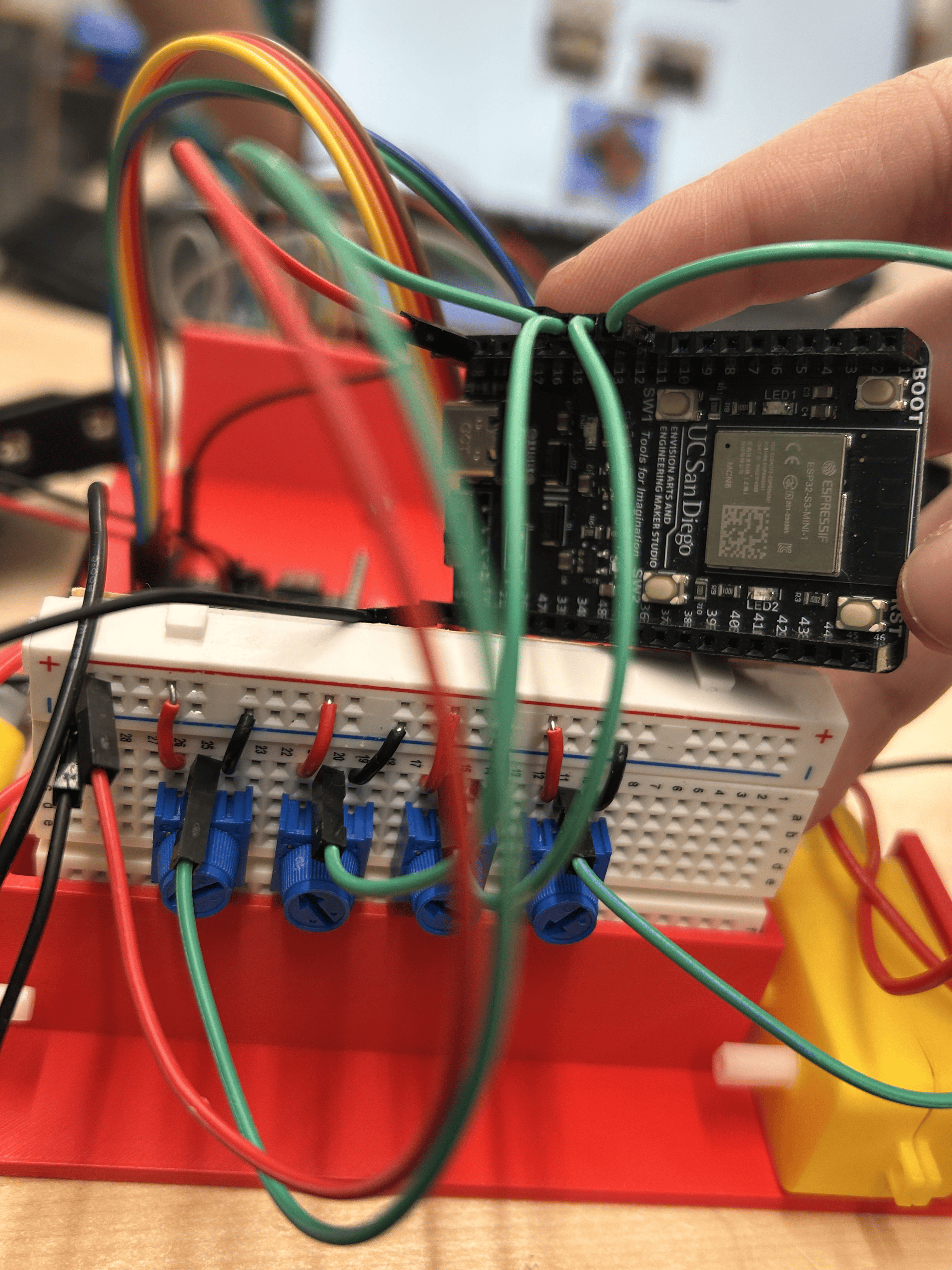
Dial in Speed, P, I, and D values on the fly — no re-uploading code. Twist clockwise to increase, counterclockwise to decrease (or the other way around, we checked).
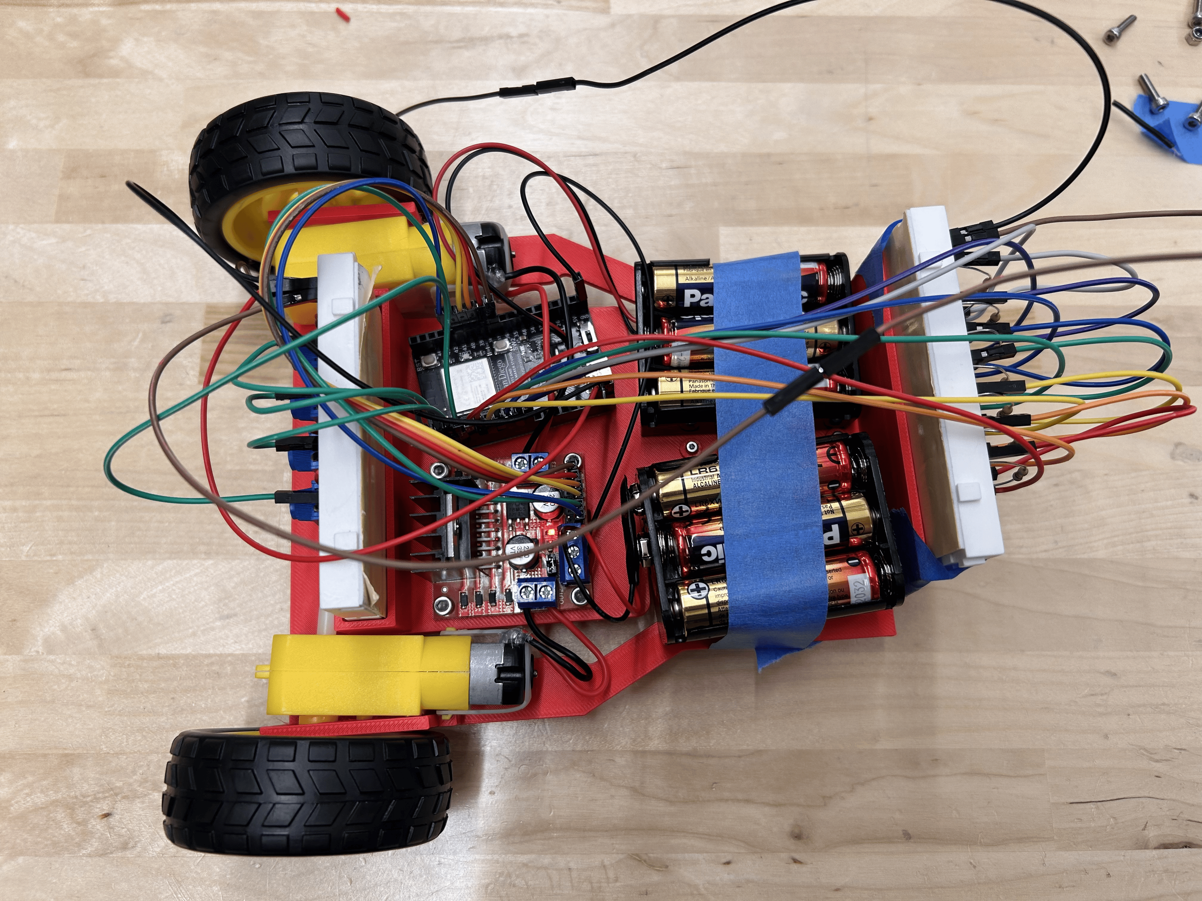
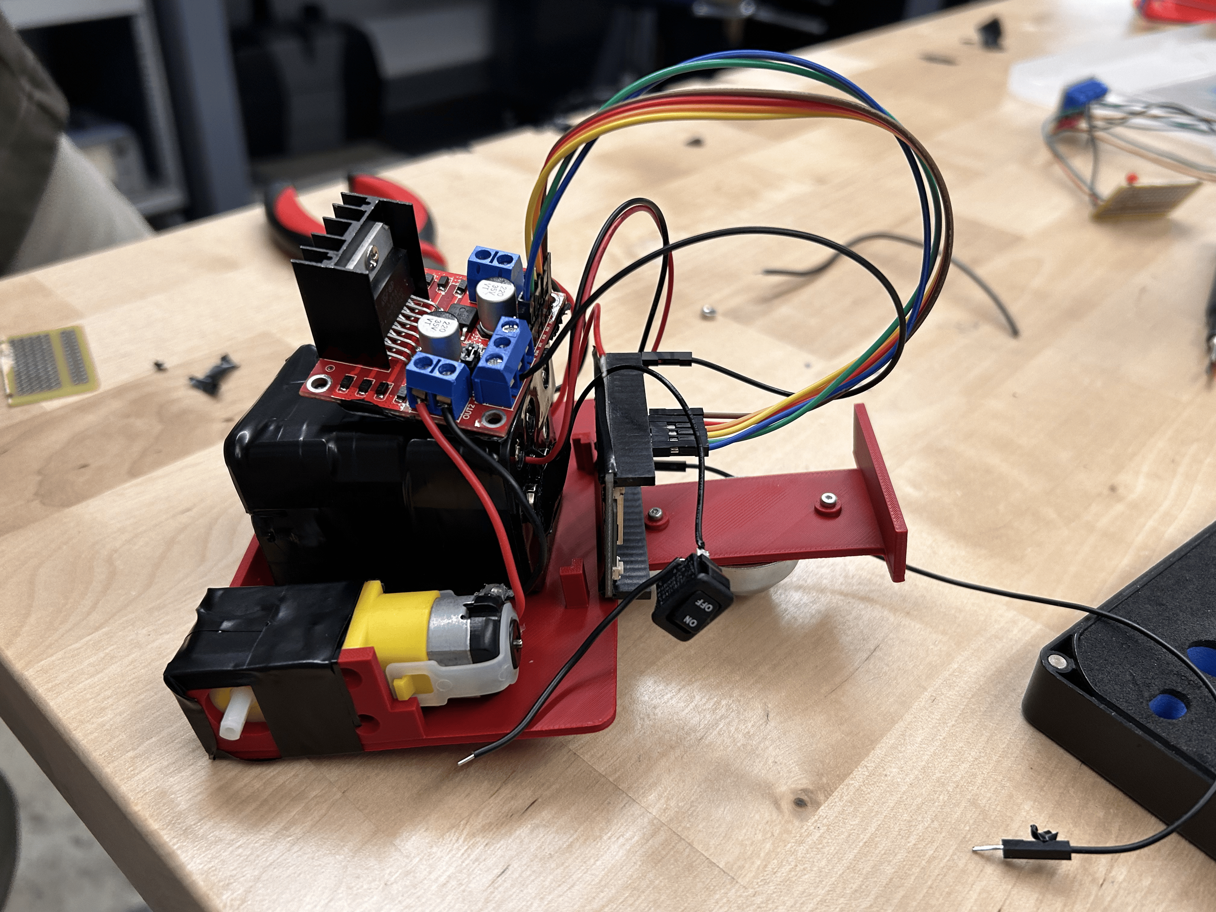
Controls two DC motors independently via PWM. IN1/IN2 set direction, ENA varies speed. Jumper removed for full variable-speed control. All grounds tied together — learned that one the hard way.
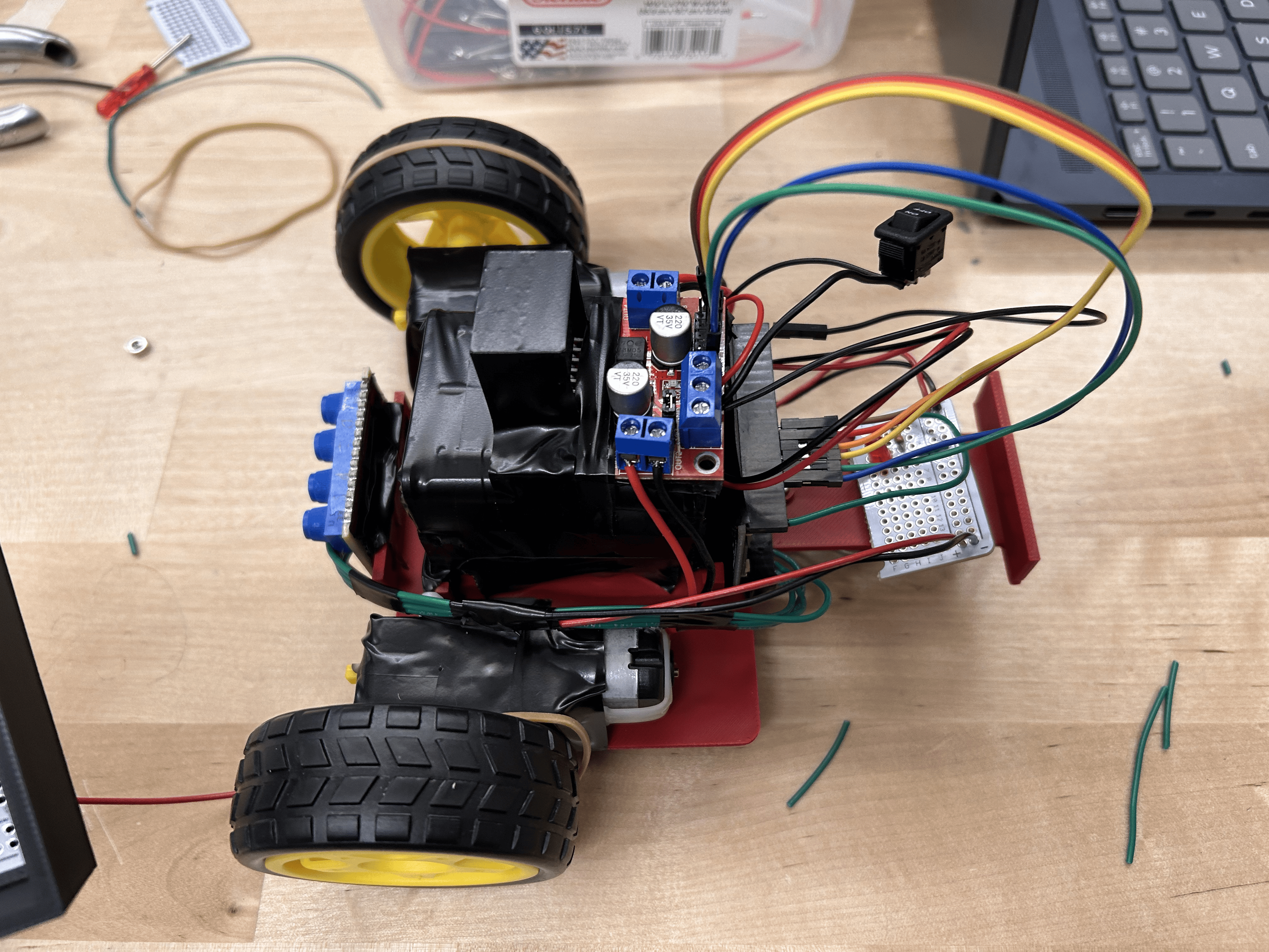
Yellow TT gear motors taped to the chassis, wires soldered and strain-relieved with a generous glob of hot glue. One caster in front keeps everything level.
Custom-designed in Onshape, printed in PLA. Modified from the base template to include mounts for the breadboard, ESP32, and the photoresistor array up front.
Step by step assembly of the finished robot:
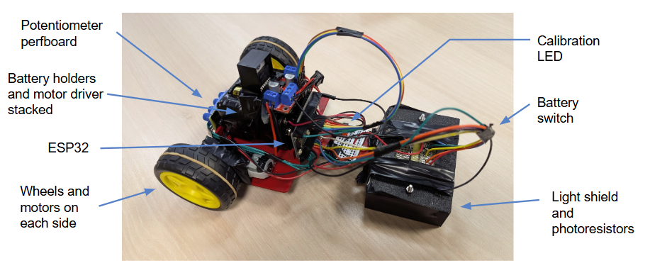
Our completed robot annotated with key features.
How we made the robot follow a line and how we tuned it.
PID (Proportional–Integral–Derivative) is a closed-loop feedback control algorithm. Our robot continuously reads the 7-sensor array to calculate how far off-center the line is (the error). The PID controller then adjusts the left and right motor speeds to correct for that error in three ways:
Correction proportional to the current error. Large error → large correction. Too high and the robot oscillates; too low and it's sluggish.
Accumulates past errors over time. Corrects for persistent bias (e.g., one motor faster than the other). Can cause wind-up if set too high.
Reacts to the rate of change of the error. Dampens oscillation and smooths out sharp turns. Acts as a brake before overcorrection.
Set higher for smoother tracks (1 and 3) and lower for trickier turns in Track 2, balancing completion time against the PID's ability to respond accurately.
Controls reaction intensity — how sharply the robot turns in response to error. Set higher for tracks with trickier turns (Track 2) to correct quickly.
Kept very low across all tracks. Accounts for accumulated past errors and forces gradual corrections for persistent drift without causing wind-up.
Uses the rate of error change to prevent overcorrecting. Higher D values balance out higher P values on the more demanding tracks.
A smoother track allows for higher speed. Lower P keeps corrections gentle on a more predictable path, and a slightly lower D is sufficient to prevent overcorrecting.
The trickiest track — speed is cut in half to give the PID time to react to rapidly changing curves. Higher P drives sharper corrections, and a higher D keeps that from overcorrecting.
The smoothest track allows the highest speed. P is slightly elevated over Track 1 for consistent turning, and D is kept higher to dampen any oscillation across laps.
Watch our robot compete on each track during competition day!
Frequency Sweep video — add here
Loop video — add here
Submitted during Week 10 — summarizing our design, build, and results.
Our scores and rankings across all three competition tracks.
Every challenge built in order.
Wired 4 potentiometers on a breadboard to act as live-adjust knobs for Speed, P, I, and D — no reflashing required. Fixed the FIX MEs in the starter code and verified each pot printed correctly to the serial monitor. Discovered that CW increases the value; swapping the wiper and power pins reverses it.
Built 7 voltage dividers using photoresistors + 10 kΩ resistors. Enabled USB CDC On Boot so values printed to serial. Tested over black and white surfaces at different heights to find the sweet spot — too close and it saturates, too far and contrast disappears. Noted that shadows from overhead lighting shift readings; a light shield will help.
Soldered wires onto both DC motors and added hot-glue strain relief over each joint. Soldered the 9V battery connector to the ESP32 (not the motor driver — max 7.4 V through that port!). Removed the ENA/ENB jumpers for PWM speed control. Wired motor driver IN1–IN4 to ESP32 GPIO pins, tied all grounds together. Coded forward/backward for 3 s each using the L298N library, then tried a figure-8. One motor ran backwards — swapped the leads on that channel to fix it.
Made a copy of the provided Onshape template and modified it: added a breadboard tray, ESP32 mount, and a front bracket to hold the photoresistor array at the correct sensor height. Sized caster mounting holes for M3×6 screws. Sent to 3D printer.
Mounted DC motors to chassis with tape. Screwed caster to the underside with M3×6 Phillips heads — snug but not over-tightened into the plastic. Fitted both breadboards, placed ESP32 in its mount, and routed all wiring. First full power-on with everything attached: motors spin, sensors read, no smoke.
Wrote the PID control loop using the photoresistor array for error calculation. Used the 4 potentiometers to tune P, I, D, and Speed live on the track. Achieved smooth line following on the straight and handled curves at competition speed.
Check out our code →Competed across three tracks: Drag Race, Frequency Sweep, and Loop.
What changed in the final week and what we'd do differently with more time.
The design process involved collaborative brainstorming, with numerous drawings and conversations between the team — especially regarding chassis layout and component placement. Through multiple work sessions, we engaged in challenges that were laborious, thoughtful, and ultimately rewarding. Working at DIB, we set up a mock track using paper and electrical tape to verify that the robot could follow lines reliably before seeding.
Throughout the project, we learned the importance of testing each component individually to root out problems early and save time during assembly. Precautions such as applying electrical tape beneath components helped prevent accidental shorts. Our design process reinforced the principle of prototyping on a breadboard before committing decisions to the perfboard. Beyond components from previous labs, we expanded our skills by wiring new hardware including motors and motor drivers. We also gained a deeper understanding of how PID controllers work and developed hands-on experience tuning them to different operating conditions.
Looking ahead, we would dedicate more time to PID tuning earlier in the process, as much of our late-stage troubleshooting stemmed from suboptimal controller parameters. We would also improve cable management from the start, since cluttered wiring made debugging more difficult and potentially introduced noise when we were trying to program and read values.
The humans responsible for this machine.
ECE · UCSD
ECE · UCSD
ECE · UCSD
Physics · UCSD
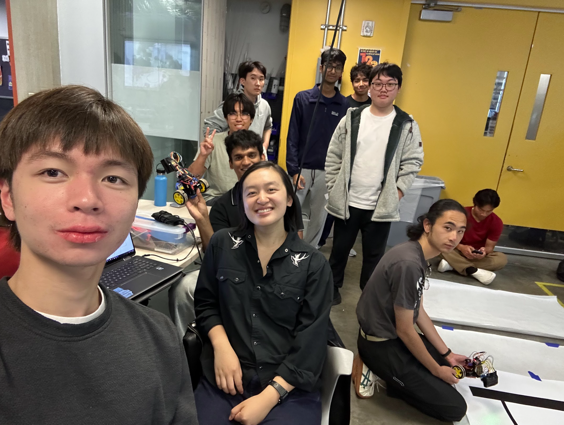
Team photo (day of the competition)